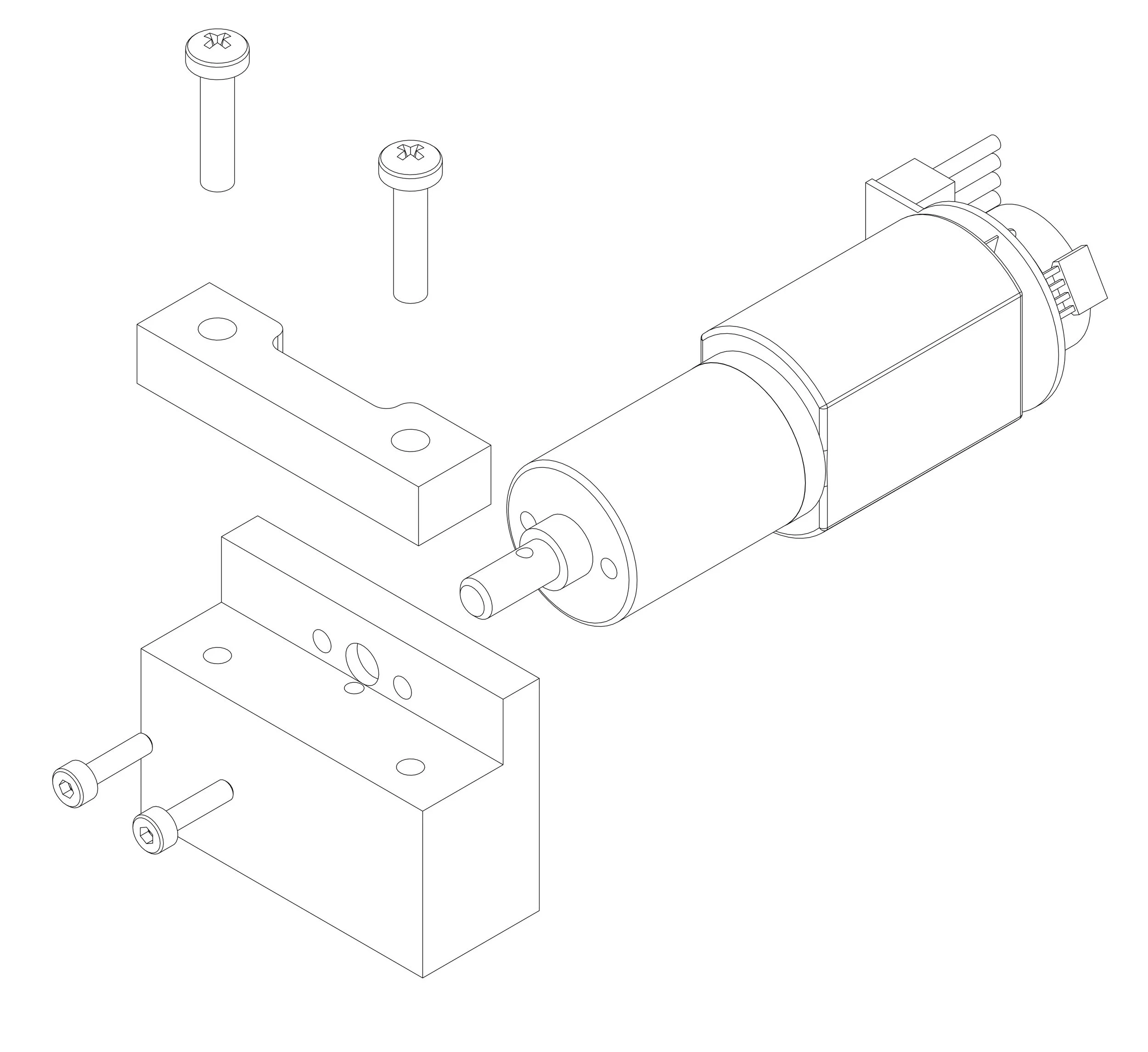
Motor Fixture

For the project I was working on at Function Engineering, we used a motor to drive a gear. Unfortunately, the motors that we purchased did not have a hole predrilled in the drive shaft through which we could thread the pin required to keep the gear in place. We needed to drill the hole ourselves; however, the dimensions of the motor prevented us from just directly clamping it in a vice. Consequently, we needed a fixture that could hold the motor in place while we cross drilled the required hole into the drive shaft.
About a month into my internship at Function, one of the engineers tasked me with designing this fixture. After multiple iterations and more than a little advice from a Function engineer, I was able to accomplish this task.
My first idea was to sandwich the motor between two pieces, so I created a design with a top and bottom piece. The pieces closely followed the contours of the motor. Both pieces were identical except for their keys: one piece had the male side and the other had the corresponding female side.
There were several problems with this design. The biggest issue was that my design was line-to-line, meaning that my part was touching the motor at too many points. Having so many contact points meant that my part would need extremely tight tolerances in order to work, leading to increased machining time and increased costs. I learned that it is best to avoid producing a part that touches another part on multiple sides, but if doing so was unavoidable, then the parts should just touch at one tangent point on each side.
Another problem with the design was that it was too complicated. Even ignoring the line-to-line issues, the contours would be impossible to machine without use of a CNC mill. Again, this would lead to increased machining costs.
The last issue with the part was that it did not sufficiently constrain or support the motor drive shaft. The drive shaft had the ability to slide in and out a few millimeters, which could lead to errors when it came time to drill through the shaft. Moreover, drilling through the drive shaft puts a large load on the shaft which could potentially damage the motor if the drive shaft is not supported.
At the recommendation of the engineer, I redesigned the fixture using a screw clamp. My new proposal looked similar to the final part except that it contained a groove for the drive shaft to rest in and a fillet instead of a right angle between the upright and flat sections of the part.
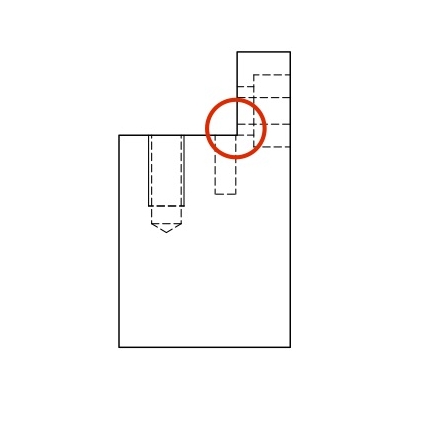
Former Location of Fillet
This design would serve but was still more complicated than necessary. Both the fillet and the groove, while not extremely difficult to machine, were unnecessary cuts. The fillet, for example, would only require that a ball end mill be used instead of a flat end mill for the last pass on the section immediately bordering the upright section. Making the fillet would require at least one additional tool change, costing more time and money as a result. The groove was similarly superfluous.
I learned a great deal about design for manufacturing during the process of creating this fixture. I learned primarily how to make the simplest and cheapest piece required for the job. One of the big differences for me was that before working on this project, I had previously designed primarily for additive manufacturing where I worked to minimize material use. Designing for machining required me to optimize for time instead. After all this work, there was nothing more satisfying than getting a steel part back from a machinist that matched my dimensions and tolerances. My first real part.

Final Part
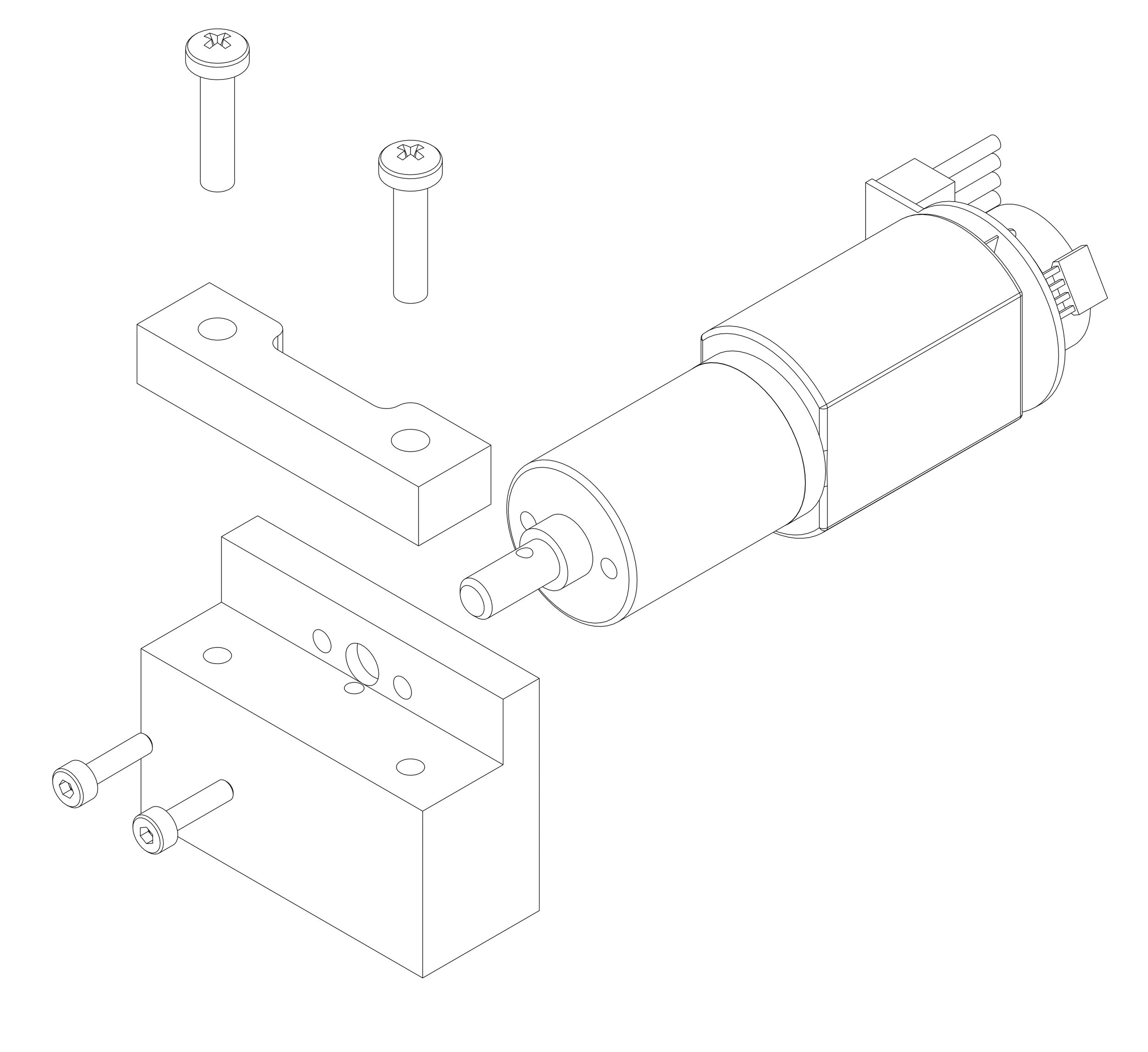
How it all comes together
All images and text are produced with permission from Function Engineering